
[Avail] Microcast Brake CNQ14K (for SHIMANO 14 CALCUTTA CONQUEST only)
![Photo1: [Avail] Microcast Brake CNQ14K (for SHIMANO 14 CALCUTTA CONQUEST only) (1)](https://www.hedgehog-studio.co.jp/phone/data/hedgehog-studio/product/20260122_de38e1.jpg)
Our Selling Price: US$23.10 [Regular Price: US$33.00]
Item Description
Model
Microcast Brake CNQ14K
Product Description
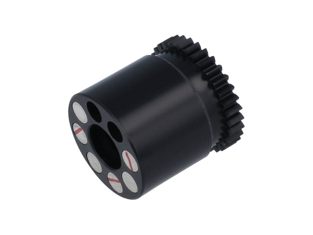
Microcast Brake CNQ14K
Magnet Brake for MicrocastSpool 14CNQ1024RI.
For casting lighter lures, a combination of PE line and a magnetic brake is recommended.
How to Install the Magnet Brake
Here we will use 15CALCUTTA CONQUEST101HG and explain it.
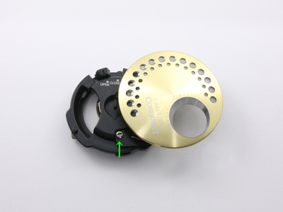
Remove the side cover from the reel body and remove the fixing bolt attached to the frame B receiver assembly.
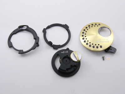
Remove each part from the removed frame B receiving assembly.
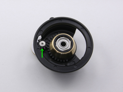
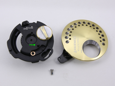
Set the external brake adjustment dial (hereafter referred to as "dial") to MIN. and turn the frame B receiving assembly over.
Remove the fixing screw of the dial and remove the BR knob gear (henceforth, the small gear).
The brake pipe gear can be easily removed by rotating it.
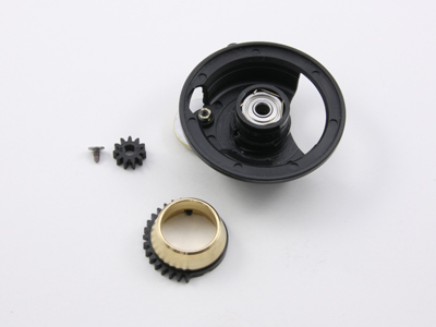
The removed brake pipe gear (gold-colored part) is not used for the magnet brake specification.
Keep it in a safe place, as it will be needed for use with the centrifugal brake.
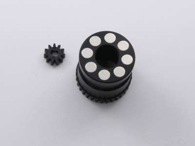
*The brake unit in the photo contains magnets in 8 locations, but the product contains magnets in 6 locations. Up to 2 magnets can be added.
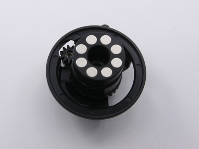
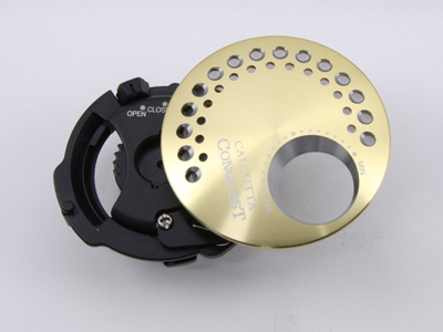
Align the dowel on the back of the brake unit with the sloping notch in the frame B receiver assembly and fit it in.
Then rotate the brake unit and push it to the deepest point.
Set the dial to an angle turned fully toward MIN. and place a small gear on the shaft of the dial.
The parallel part of the gear hole should be aligned with the parallel part of the dial shaft, but if the small gear is pushed in too hard at that time, it may be damaged.
It is then secured with a fixing bolt.
The rubber ring is cushioned and a little tight, but be careful not to tighten the fixing bolt too much as it will crush the threads in the shaft.
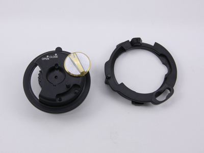
When assembling, the frame B receiving cams and the body B cam levers are stacked as shown in the photo.
The two overlapping parts are attached to the frame B receiver assembly as shown in the photo.
Place the cup assembly between the bronze-colored washers and temporarily fix it with the fixing bolt.
There is a small protrusion on the arrow. Twist the protrusion so that it is inside the body B, and then tighten the fixing bolt firmly.
When assembled correctly, the previously mentioned protrusions will not be visible from the outside.
Assembly is now complete.